Meridian Drift Scanning
Sun, 02/20/2011
A 3 metre solid fibre glass dish due to its size and weight is not really the most practical thing to use in a suburban back yard and a motor driven system to control elevation and azimuth would require twice the area.
Consequently, the dish will be aligned in a North-South orientation where only the elevation is controlled. Then using a the method called Meridian Drift Scanning the earth's rotation can be used to scan many radio objects in the sky over 24 hours.
The meridian can be defined as a line that runs from your southern most horizon point (180 degrees azimuth) through the zenith (directly overhead) to the northern most point on the horizon (0 degrees azimuth). An antenna pointed along this line will over the period of a day cross all objects in the sky within a certain range of declination (determined by the beam width).
Once the dish is aligned in this manner we can then use a software package called Radio Eyes to predict what the radio telescope will see at any given time and during a full rotation of the earth. In this example below, the 3 Metre dish is pointing to the South (azimuth 180 Degrees) at an elevation of 80 degrees with an estimated beam width of 2 Degrees at 1.42Ghz.
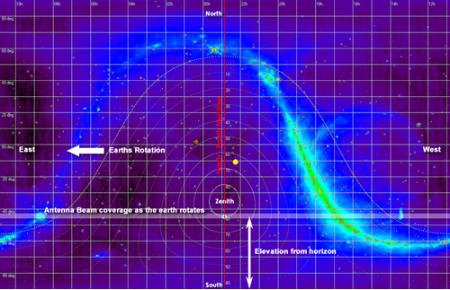
The image above the galactic plan has been distorted to reflect what the antenna would image in a full raster scan using the earth's rotation. Below is what it look like when the image is corrected.
As seen in radio spectrum at 408MHz

As seen in the visible spectrum by the human eye
A lot of amateur Radio Telescopes use the Meridian Drift Scanning method because it saves considerable amounts of hardware in the form of drive systems and simplifies the mounting arrangements required to 'get operational'. It does not tend to compromise the abilities of a Radio Telescope as to what it can 'see'.