Adelaide Hills Radio Telescope
Mon, 11/23/2009
21cm Radio Telescope
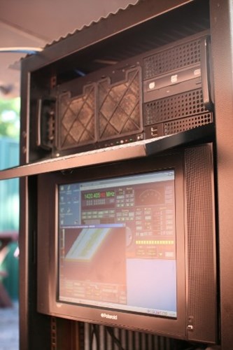
My 21cm radio telescope consists of three primary components, an antenna, a receiver and a computer.
Antenna
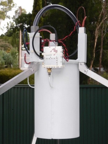
The antenna is a 3.05 metre diameter parabolic reflector with a focal length of 1.172 metres. A cylindrical feedhorn is mounted above the reflector in prime focus configuration. The reflector was manufactured by Siemens for Telecom Australia (Telstra Corp.) and has spent much of it's life as a communications link at the top of Mt.Macedon in rural Victoria. All modifications and conversion to the present configuration have been carried out by myself and my brother inlaw, Tony Davies.
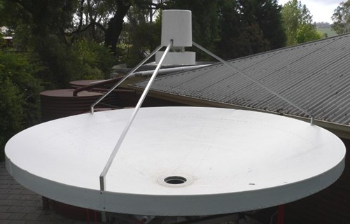
The beamwidth of the antenna is 0.07 radians which covers approx 4° of the sky at any one time. The antenna is mounted in a drift scan configuration, aimed at the site zenith point. It is currently located in the Adelaide Hills, Grid reference - PF95ke.
21cm Telescope Receiver
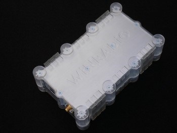
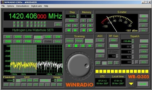
- The WinRadio G305e/PD scanning multimode software defined receiver (SDR) has been selected for the signal conversion stage. This Australian made SDR is one of the first commercial off the shelf receivers available with a universal serial bus (USB) interface. winradio.com.au/home/g305e.htm
- The usual SDR configuration for this application is lower single sideband, subsequent digital signal processing (DSP) stages can be selected to suit any number of requirements. The Professional Demodulator option was included to allow selectable intermediate frequencies (IF) bandwidths up to 15kHz in 1Hz steps.
Front End Operation
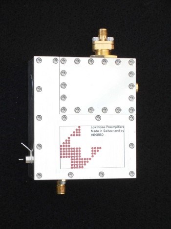
Radio power signals arriving from directions close to the axis of the parabolic antenna are focused by reflection to an antenna feedhorn optimised for operation at 1420MHz. Antenna gain is assumed to be approx. +30dBi. Signals then pass through two L band probes phased 90 degrees apart and coupled to a pair of low noise amplifiers (LNA) with noise figures of ≤ 0.2dB at 1420MHz. The LNAs were built, adjusted and tested as a matched pair by Dominique Faessler, HB9BBD - hb9bbd.ch. Each LNA provides an input 40MHz bandpass filter and two amplification stages producing 40dB of gain. The bandpass filters prevent out of band signals such as those generated by geostationary satellites and other man made interference sources from producing intermodulation products in the SDR's image rejection mixers.
- In the current configuration, the two signals are then combined with a 90° quadrature hybrid coupler and fed via low loss cable to one SDR. In order to minimise cable losses, the SDR is housed directly underneath the antenna. Sometime in the future I plan a dual SDR configuration based on the USRP II which will allow each LNA output to be fed via low loss cable to each SDR, the incident & quadrature (I & Q) signals allowing more complex DSP to further reduce noise effects and enable other enhanced signal detection techniques.
- The current SDR is a dual conversion superhetrodyne type with demodulation modes for amplitude modulation (AM) and narrow band frequency modulation (FM). Specified sensitivity at 1420MHz for 500Hz IF bandwidth in CW mode for 10dB S/N is -119dBm (250nV).
Receiver Operation
WiNRADiO G305e Operation
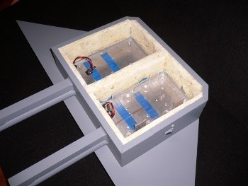
The incoming signal is filtered and amplified (switchable), then fed to a mixer. Here it is mixed with the first local oscillator, which is performed by a direct digital synthesiser (DDS) with a phase locked loop (PPL). The resulting 109.65MHz intermediate frequency is filtered using a 4-pole crystal filter with an IF bandwidth of 15kHz, and then amplified. The second mixer again uses a DDS with a PLL to mix the 109.65MHz signal down to the last intermediate frequency, which is 12kHz. The second IF bandwidth is adjusted in software. The Professional Demodulator option allows the second IF bandwidth to be continuously variable from 100Hz to 15kHz. Both DDS circuits derive their reference frequency from an internal 20MHz reference oscillator. Frequency stability is optimised by operating each SDR in small temperature controlled enclosures, heated from underneath by non-inductive resistive elements and cooled from above by peltier thermoelectric modules.
Automatic gain control (AGC) can be performed in the first IF stage, based on the level of the second IF output. As the IF bandwidth of the first IF stage is 15kHz, the AGC action is delayed until the dynamic range of the first IF stage is fully utilised – this is in order not to cause desensitisation of the SDR in the presence of neigbouring strong signals, falling within the 15kHz IF bandwidth. The resulting variation in audio output is then compensated for in software, using Audio AGC in the software demodulator. In normal radio telescope operation, both the AGC modes are disabled and the gain of the IF amplifier is set for optimum sensitivity or signal to noise ratio. The SDR's inbuilt 12dB preamplifier and 18dB attenuator are both switchable to enhance front end performance.
The demodulated output is digitised and sent via USB to the computer for further DSP by either:
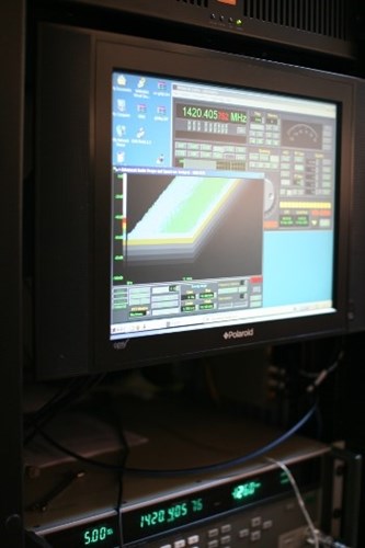
the WinRadio Advanced Digital Suite software which incorporates an Audio Oscilloscope for voltage/time displays and an Audio Spectrum Analyser for frequency/time displays.
- A DC-10kHz(max.) fast fourier transform display and several types of waterfall displays are available using the internal DSP configuration.
- A DC-20kHz(max.) fast fourier transform display and several types of waterfall displays are available using the computer's integrated sound card configuration. Recording of data to sound (.wav) files is possible using manually set, conditional signal or squelch controlled recorders.
the WinRadio Digital Bridge Virtual Sound Card software makes it possible to interface the SDR's IF output directly to third party decoding/DSP software such as Winrad or Linrad.
Interface the SDR's AF output directly to third party DSP software such as Spectran.
Audio generation on the computer's integrated sound card for additional DSP and/or monitoring.
21cm Telescope Computer(s)
- Currently using a Pentium 4 processor 641 on an ASUS P5PL2-E motherboard with 2Gb of DDR2 SDRAM. Onboard data storage capacity is 2Tb, capable of holding about 6 months of raw data in .wav format. Additional data storage, processing power and memory capacity will be increased as required. The PC is mounted directly below the reflector in a 19" rack due to the 5 metre USB cable length limitation. Shielding techniques have been used extensively to minimise electromagnetic interference generated by the PC affecting reception.
- The WinRadio Receiver software and WinRadio Advanced Digital Suite software require Micro$oft products be used (begrudgingly) for an operating system. Windows 2000 Service Pack 4 has been selected to allow use of several different software packages already developed and employed globally by weak signal amatuer radio enthusiasts/operators. Post processing of signal data can be carried out on notebooks and other PC's running Ubuntu Linux 10.04 O/S.
Digital Signal Processing
-
Waterfall Spectrum Analysers
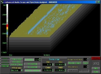
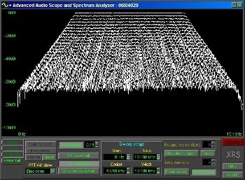
- The waterfall spectrum analyser makes it possible to display the evolution of an FFT spectrum over time. Each new line of the display window represents a new spectrum trace; every point of the line corresponds to a particular frequency and its colour to the signal level at that frequency. The range of signal levels and time intervals displayed can be varied, depending on the software in use.
WinRadio Advanced Digital Suite software FFT spectrum analyser and waterfall displays allow seamless realtime signal monitoring. It is limited by a fixed display size, and signal level resolution. There is no function to capture the display over time into images for quick analysis.
Spectran is a good shareware software tool with a dual function of FFT analyser and waterfall display with image capture in jpg files. It is somewhat limited in resolution by a fixed display size. WinRad is a very good shareware software tool with similar features to Spectran (same authors) but more powerful features such as inbuilt demodulation functions, high bandwidth capabilities and full screen display functionality.
HI Spectral Line Monitoring
So how can I effectively use a narrow bandwidth receiver with a basic frequency stability specification of parts in 10E-6, to monitor frequencies in the range of 1.4E+9. One way would be to lock the local oscillator (LO) to a relatively stable frequency source. The G305e SDR does not have the capability to do this without serious modification, something I would prefer not to do. I do have a signal generator that I can use to inject a nominal or offset signal into the front end of the receiver but it's basic frequency stability is about the same as the receiver, possibly doubling the (worst case) error. The signal generator does have the capability to phase lock to an external 10MHz frequency standard.
Enter the Thunderbolt
Recently, I added a Trimble Thunderbolt GPS Disciplined Oscillator to the inventory for a couple of reasons/projects: (see the GPS Timing page)
- Use it somehow to stabilise the G305e SDR on the telescope for this project.
- Use it to generate a stable and accurate LO for two USRP SDRs configured as I & Q inputs on the telescope for this project.
- An accurate UTC time source for observing and recording occultation events (optical astronomy)
- An accurate UTC time/frequency source for synchronising to a long baseline interferometer, now that the RA group is developing the HFI project.
If I use the Thunderbolt to stabilise the frequency of the signal generator output, all I should need to do is track the signal at an offset of say -100Hz (1420.40566MHz) and monitor any response other than the reference trace.
This would display any HI responses from sources at the nominal 1420.40576MHz
- local sources within the Milky Way galaxy do not have large doppler shifts (red shift below nominal) or blue shift (above nominal).
- Other HI signals with significant offsets would be from outside the Milky Way Galaxy and probably not within the 15kHz maximum IF of the SDR.
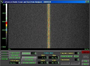
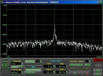
2 images of the injected 100Hz offset signal, level is about -105dBm @ approx. 1 metre from the feedhorn.
The G305e SDR has an Automatic Frequency Control (AFC) function which will allow this to work, but there are several minor disadvantages with this arrangement.
- the receiver requires a significant input signal level to operate the AFC correctly
- the reference trace is always centred on the display, halving the usable available bandwidth
- sources red shifted by 90 to 110Hz would be masked by the reference signal response.