Jupiter Emissions Reception
28/10/2021 -John
From the NASA Jove newsletter
There is now a 2 U Cubesat - KOSEN-1, in low Earth orbit (LEO) with an software defined radio (SDR) to monitor Jupiter's radio emissions (with 2 other experiments).
further details at https://radiojove.gsfc.nasa.gov/newsletters/2021Aug/
Tue, 09/27/2011-Peter
Antenna Array
It has been a couple of years since erecting my original Radio Jove single dipole antenna but in 2011 I decided that some improvement was required to the way I was trying to receive the decametric Jovian emissions. The impedance chosen for the antenna and transmission lines is 50 ohms, primarily because this suits my (and ASSA's) receivers and 50 ohm systems are easy to test with available equipment. The original dipole had been 'tuned' using a demonstration Agilent N9912A RF Analyser so I was fairly confident that the antenna was working well. This has now become the North Dipole of this array, an identical copy was constructed from the same 14AWG wire and the same LMR-195 coaxial cable, forming the South Dipole. Another length of LMR-195 was cut to set a delay of 135° at 20.1MHz and this was added to the transmission line from the North Dipole to steer the beam down toward the northern horizon to suit the current transit elevation of Jupiter.
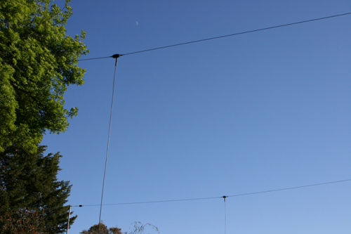
The Radio Jove Array looking to the North. That is Luna (the moon) in the image, not Jupiter.
Finally, I constructed a three arm divider (16.66ohms/arm) to combine the dipoles and output any signals to the receiver. The specific resistance was obtained by using a couple of 1206 SMD resistors paired in parallel. A resistor pair is placed in series between each of the sources and the load, forming a correctly matched impedance in each direction. The contents of the enclosure are encapsulated in Dow Corning 3145 RTV to stabilise the temperature and humidity of the resistors.
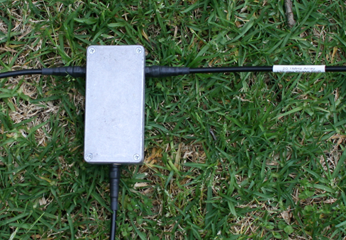
My 50 ohm divider/combiner with SMA connectors and self amalgamating tape to keep out the weather
Recently, an opportunity came up to use an Agilent 8753ES Vector Network Analyser at home so I made the most of it and took a couple of plots between 18MHz and 22MHz. The following images show the SWR of each dipole and their combined effects together.
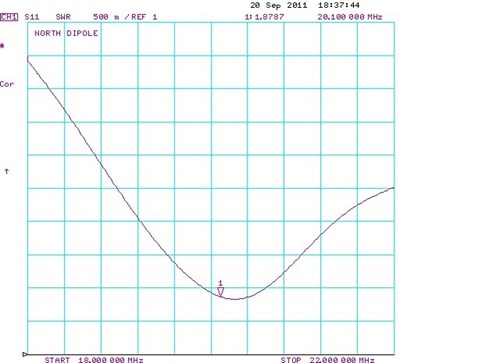
The North Dipole is pretty close to optimal at 20.1MHz.
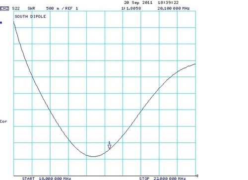
The South Dipole could use a little bit of trimming down.
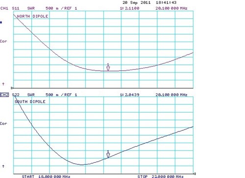
Note the difference between the responses when both dipoles are driven at the same time.
The South Dipole really needs to be cut shorter to bring the dip to the centre. The response of the both
dipoles have flattened out considerably and the SWR of both dipoles has increased (degraded).
Receivers
WiNRADiO G305e: There is additional information on the operation, capabilities and features of this receiver here.
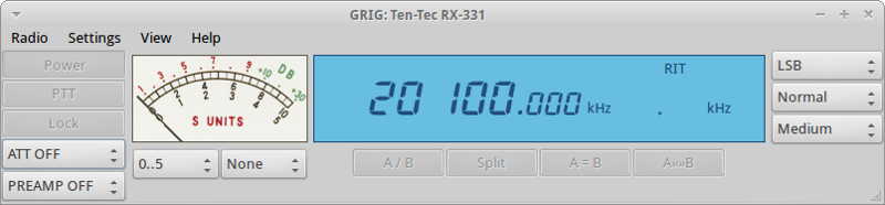
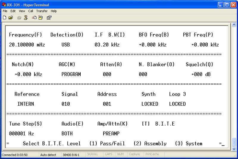
Ten-Tec RX-331: There is additional information on the operation, capabilities and features of this receiver here.
Ten-Tec 1056: They occasionally come up on ebay, but are no longer in manufacturer.
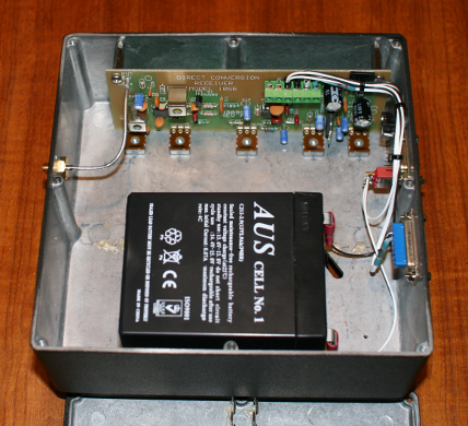
A single TenTec 1056 receiver with battery for very low noise operation
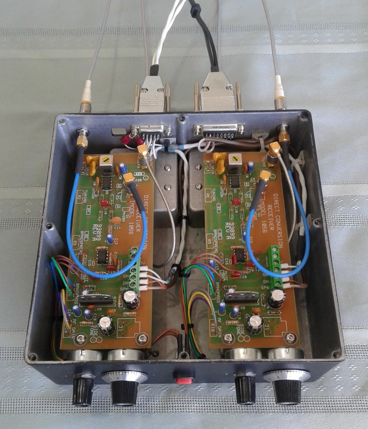
A pair of TenTec 1056 receivers with a common local oscillator for interferometer work built by Peter.